Connector nut tightening machine selection starts with the connector assembly instruction and the parts that must be restrained. A motorized tightening head can repeat a movement, but the fixture, thread condition and acceptance method determine whether that movement produces a usable assembly.
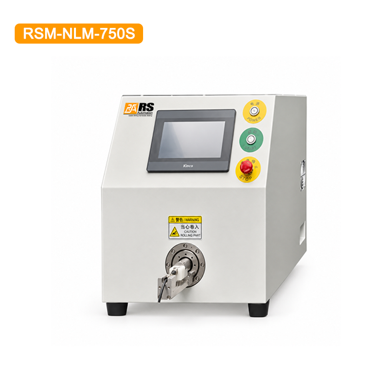
This article develops the connector-locking section of our wire harness assembly support equipment overview. It is a practical review framework for buyers and process engineers evaluating the RSM-NLM-750S single-head connector nut tightening machine.
1. Identify exactly which nut is being tightened
A cable assembly may contain a backshell, cable gland, coupling ring and other threaded components. These parts do not necessarily use the same instruction or acceptance check. Send the drawing and identify the particular threaded interface; a photograph labeled only “aviation connector” is insufficient to define the operation.
Record connector and nut part numbers, thread details, component materials and the permitted tightening method. Identify the condition in which parts reach the workstation, including whether contacts, seals and cable supports have already been fitted. The assembly drawing should determine the order of operations.
Do not infer an acceptable tightening value from a connector family name or from a visually similar part. Use the exact supplier instruction and clarify units and tolerances. The currently published RSM-NLM-750S table abbreviates its torque-range unit; obtain a confirmed engineering specification rather than turning that abbreviation into a guaranteed N·m range.
2. Establish the fixture reaction path
The tightening head applies a turning action that must be reacted somewhere. Identify which component the fixture holds and how it prevents unwanted rotation. Review the gripping surfaces, component support and the direction of loading with a sample assembly.
A fixture that holds firmly can still be unsuitable if it marks the housing, compresses a seal area or strains an attached cable. Check access to the nut without gripping delicate features. Include nearby connector branches, cable bends and accessories when evaluating clearance.
The product listing describes customizable, replaceable fixtures for different workpiece profiles. This supports a connector-specific review; it is not evidence that one supplied fixture accepts every connector. Ask which tooling is included, which variants require another fixture and what checks are required after a changeover.
Review loading as well as tightening
Observe how the operator identifies the correct component, places it in the fixture and starts the cycle. Confirm how the thread is engaged and how a poor start is recognized. Do not assume automatic cross-thread detection, part-presence monitoring or recipe verification unless those functions are demonstrated on the proposed configuration.
3. Torque mode and rotation-count mode answer different questions
| Review point | Torque-based operation | Rotation-count operation |
|---|---|---|
| Process instruction | Confirm the specified torque, units and tolerance | Confirm the starting condition and required rotations |
| Setup question | How is the setting established and checked on this configuration? | How is the initial engagement position controlled? |
| Important variation | Thread condition, friction and component support | Engagement depth, starting position and thread condition |
| Acceptance | Use the agreed assembly inspection; a setpoint alone is insufficient | Verify the finished assembly; rotations alone do not prove torque |
The RSM-NLM-750S listing identifies torque, rotation-count and loosening modes, with a 7-inch HMI for parameter settings. Mode availability does not decide which mode is correct for your connector. Make that decision using the connector manufacturer’s instructions and the agreed validation method.
For a torque-controlled process, ask how the proposed system determines its stopping condition and how that result is verified. For rotation-count operation, define the point from which counting begins. Changing the starting engagement can change the finished condition even when the programmed count is unchanged.
A connector that looks fully seated may still need other mechanical or electrical checks. Tightening alone does not establish waterproof performance, contact integrity or compliance with an environmental rating. Apply any required tests to the completed assembly using its approved procedure.
4. Run a trial that includes normal production variation
Supply representative connector components and cables. Include the variants that change access or restraint, such as different housing profiles, cable sizes or already-installed accessories. Agree how many samples are needed and what constitutes a pass before evaluating results.
- Document the starting assembly. Confirm part identity, required preceding operations and the condition of threads and seals.
- Review fixture contact. Photograph the support points and check for movement or damage during the cycle.
- Confirm the selected mode. Record the program revision and settings with their units.
- Inspect finished pieces. Apply drawing-based checks, including housing condition and any required mechanical or electrical verification.
- Include interruptions and changeover. Review restart and first-piece approval using the intended work instruction.
Separate machine time from operator time. The published output range is expressly dependent on manual feeding. A useful capacity discussion therefore covers locating the part, loading, thread engagement, tightening, unloading and inspection, including the effect of rejected parts.
5. Link identification, assembly and packing without mixing their roles
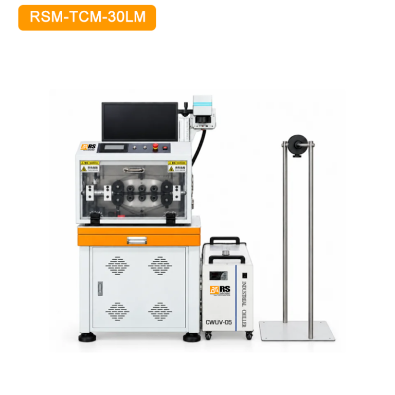
Correct identification helps keep connector variants and job instructions associated. If your process uses prepared identification sleeves, the RSM-TCM-30LM tube marking and cutting machine is an upstream option to assess separately. It does not verify the connector-tightening result.
Our D-sub assembly preparation and inspection guide illustrates why contact assignment, insulation and backshell planning are separate checks in a connector workflow. Its solder-cup procedure should not be copied onto a different connector type or used as a tightening specification.
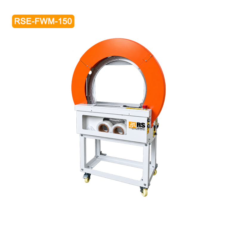
At final handling, RSE-FWM-150 film bundling equipment may help organize completed assemblies. Check that the bundle arrangement does not load connector housings or hide information needed for final inspection. Packing is a later operation with its own acceptance criteria.
What should the production record contain?
Record the exact part family, fixture identification, work instruction, mode, program revision, inspection method and first-piece result. Define who may change settings and how an altered setup is approved. If traceable electronic records or external system integration are required, specify them in the enquiry and confirm availability; do not infer them from the presence of a touchscreen.
Questions buyers should resolve
Can one fixture cover several connectors? Possibly, but only after checking geometry, support and access for each variant. A shared industry application is not proof of shared tooling.
Does the machine eliminate inspection? No. Agree how the finished result is verified and what triggers a stop or recheck. Automated movement does not replace product acceptance.
Is the highest output the best selection criterion? Compare accepted assemblies per shift, operator handling, changeover and verification requirements. A nominal speed is only one input to that decision.
Send your connector drawing and tightening requirements to RS Automation, together with sample components, cable dimensions, product mix and target output. Ask for a fixture proposal and a documented trial on the intended configuration.
Sources and review scope
Model features and the photograph were checked against the linked RSM-NLM-750S product page on October 26, 2026. WHMA’s acceptance-standard overview provides cable-assembly context; it does not supply a universal connector torque. This article presents selection and verification questions, not a customer test report or certification claim.