Choosing a crimping applicator starts with the terminal and wire combination, followed by the press interface. A suitable wire-size range is only one part of the decision. Terminal strip layout, feed direction, press stroke, shut height and tooling geometry must also match the job.
This guide explains how to compare side-feed and end-feed applicators, screen 30 mm and 40 mm press configurations, and prepare the information needed for a tooling review. It also shows where special terminal applications require a different approach.

1. Match the applicator to the terminal first
Begin with the exact terminal part number rather than a connector brand alone. Provide a drawing showing the crimp barrel, material thickness, carrier strip and terminal pitch. For reel-fed terminals, include a photograph showing how the terminal sits on the strip and how the strip enters the tooling.
Then specify conductor cross-section, strand construction and insulation diameter. Two wires with the same cross-section may have different insulation dimensions or strand constructions. The tooling review therefore needs the actual wire and terminal combination, not just a nominal mm² value.
Keep the terminal manufacturer’s application specification available. For example, Molex identifies its Application Tooling Specification as the source for crimp height, pull force, strip length and applicable terminal information. Use the requirements for your own terminal; numerical limits from an unrelated terminal are not transferable. Molex application tooling documentation guidance.

2. Side-feed vs end-feed: follow the terminal strip
A side-feed crimping applicator and an end-feed crimping applicator handle different terminal strip arrangements. Neither is a universal upgrade over the other. The appropriate choice depends on terminal orientation, carrier location, feed path and the required tooling configuration.
Send the supplier a strip sample or clear photographs from above and from the side. Confirm the proposed feed direction against the actual terminal before ordering. A model suffix alone is insufficient evidence of the required configuration.
Also distinguish feed direction from feed mechanism. “Side-feed” and “end-feed” describe the arrangement; “pneumatic” and “mechanical” describe how the terminal feed is actuated. Both details belong on the selection checklist.
3. Check press stroke and shut height separately
Press stroke and shut height describe different machine dimensions. Matching a 30 mm or 40 mm stroke does not establish that the applicator can be installed and set correctly. Verify the required shut height, base mounting, ram connection, working clearance and feed actuation arrangement as well.
The published specifications illustrate why these checks matter. RSA-JNA-20S lists a 30 mm stroke and 119.7 mm shut height. RSA-ENA-20E lists a 40 mm stroke and 135.8 mm shut height. Both list a 0.08–6 mm² wire range, but that shared range does not make the two applicators interchangeable.
4. Compare product examples by the selection question
| Selection question | Product example | Published screening information | What still needs confirmation |
|---|---|---|---|
| Need pneumatic side feed with a 30 mm stroke? | RSA-JNA-20S side-feed pneumatic crimping applicator | 0.08–6 mm² wires; 119.7 mm shut height; adjustable feeding speed. | Terminal strip, pitch, press interface and selected machine configuration. |
| Need end feed for a 40 mm press configuration? | RSA-ENA-20E end-feed pneumatic applicator | 0.08–6 mm² wires; 40 mm stroke; 135.8 mm shut height. | Terminal geometry, mounting and feed actuation. |
| Screening an end-feed application with larger wires? | RSM-ENA-40E crimping applicator for 3–15 mm² wires | 3–15 mm² wire range; pneumatic end feed; 135.8 mm shut height. | Terminal drawing, required forming geometry and press configuration. |
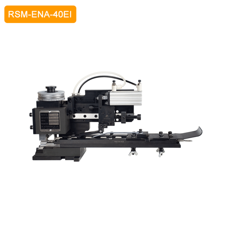
| Does the operation include an insulator push-on crimp? | RSM-ENA-40EI insulator push-on crimping applicator | Specified for insulator push-on applications; 0.02 mm C.H./I.H. adjustment resolution over a 2.0 mm range. | Exact terminal and insulator arrangement; machine setup and finished crimp requirements. |
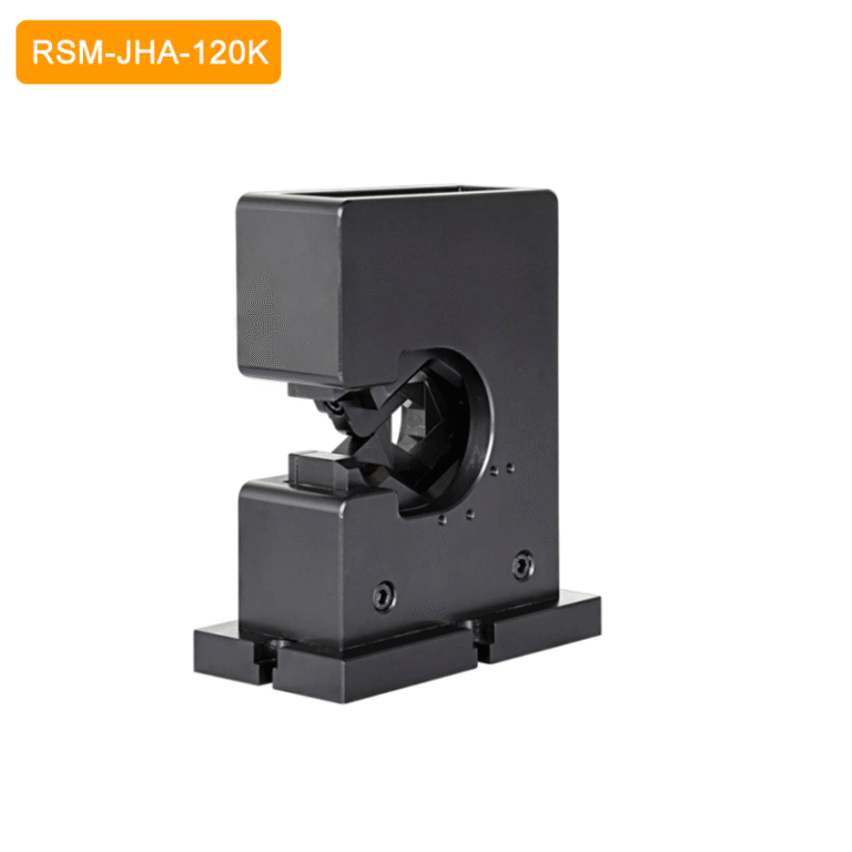
| Does a right-angle terminal or large head require a different tool opening? | RSM-JHA-120K open-end hexagon crimping applicator | Hexagon crimping; listed 10–120 mm² wire range; intended for right-angle terminals or terminals with large heads. | Terminal access, crimp profile, tooling dimensions and suitable press. |
These examples are an initial shortlist, not a compatibility approval. The specified wire ranges do not mean that every terminal within those ranges can be processed without terminal-specific tooling.

5. Confirm compatibility with the actual crimping machine
If you are sourcing a replacement crimping applicator, provide the existing tooling model and press model together. Add photographs or drawings of the base plate, ram connection and terminal feed arrangement. Confirm pneumatic supply and machine control requirements where applicable.
RSA-JNA-20S product information lists selected ShinMaywa, JAM and KODERA semi-automatic crimping machine applications. This does not establish compatibility with every machine from those brands or with every automatic processing line. A search for a JAM-style replacement crimp die should still lead to a model-specific interface and terminal check.
For an automatic crimping machine, also review the wire transfer path, tooling clearance, feed timing and any monitoring or control requirements. Ask for confirmation for the exact machine and terminal combination rather than relying on “automatic-compatible” as a general description.
For the more specialised insulator process, read the RSM-ENA-40EI selection guide for insulator push-on crimping.
6. Validate a sample before releasing the tooling to production
Agree the sample acceptance requirements before the trial. Check the finished crimp against the terminal manufacturer’s specification and the customer’s requirements. Relevant checks may include conductor crimp height, strip length, insulation position, visual condition and specified pull-force testing. Use cross-section examination where the application requires it.
Keep adjustment resolution separate from finished crimp performance. A 0.02 mm adjustment increment describes the setting mechanism; it is not a guarantee that every completed crimp will meet a ±0.02 mm tolerance. Sample results and process checks must support the production decision.
7. What to send with an applicator enquiry
- Terminal: part number, drawing, material information, strip sample and feed orientation.
- Wire: cross-section, conductor construction, insulation diameter and material.
- Machine: manufacturer, model, stroke, shut height, mounting and ram interface.
- Production: manual loading or automatic wire transfer, intended cycle rate and changeover needs.
- Acceptance: required crimp dimensions, inspection method and sample approval criteria.
Once the terminal process is defined, review the surrounding assembly tasks separately. Our wire harness assembly support equipment overview covers identification, connector nut tightening and bundling operations beyond the crimping station.
Frequently asked questions
Can one crimping applicator process every terminal within its wire-size range?
No. The wire-size range is a screening specification. Terminal barrel geometry, material thickness, carrier arrangement and the required crimp profile must also match the tooling. Confirm the exact terminal and wire combination.
Can a 30 mm applicator be used on a 40 mm stroke press?
Do not assume interchangeability. Stroke, shut height, mounting and the feed mechanism must be checked against the machine and applicator specifications. Obtain confirmation for the proposed setup before installation.
Is RSA-JNA-20S a replacement applicator for JAM machines?
Its product information lists JAM semi-automatic machine applications, but this is not universal replacement approval. Confirm the JAM machine model, terminal part number, mounting and feed arrangement for the required configuration.
What wire sizes does RSA-JNA-20S support?
The published range is 0.08–6 mm². The specification also lists side feed, a 30 mm stroke and a 119.7 mm shut height. Suitability still depends on the selected terminal and wire construction.
Does adjustable feeding speed make an applicator suitable for an automatic line?
Not by itself. The press interface, terminal feed timing, wire transfer clearance and control arrangement must also suit the line. Validate the proposed configuration with the actual terminal and wire.
Select the terminal process before selecting the model
Use the terminal drawing and wire specification to define the tooling task. Then confirm feed direction, press dimensions and sample requirements. This sequence produces a more useful shortlist than choosing a model by wire range or machine brand alone.
Send RS Automation your terminal drawing, wire specification and machine model for a configuration review.
Product examples were checked against the linked RS Automation pages on 27 October 2026. Molex documentation is cited for general tooling-selection context; it does not establish approval or endorsement of the RS Automation products.