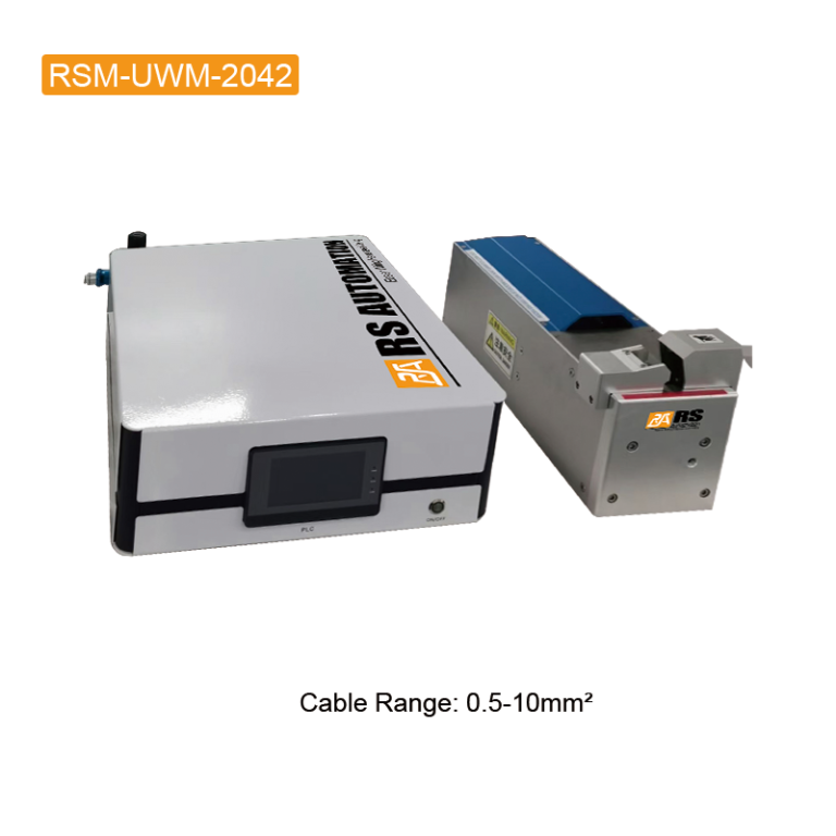
Solder fume extraction should be considered when planning a wire harness soldering workstation, alongside joint preparation, heating control and inspection. A compact extractor is useful only when its hood can collect the fume where the operation takes place. The machine rating alone cannot show whether a particular bench arrangement provides effective capture.
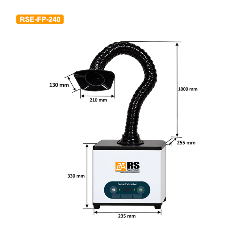
This guide explains how to evaluate the RSE-FP-240 desktop fume extractor for a single workstation, position its extraction arm and establish practical maintenance checks. It also connects extraction planning with the soldering and conductor-joining topics covered in our existing technical guides.
Start with the soldering operation, not the fan rating
Record the solder and flux used, the location of the heated joint, how long soldering occurs during a shift and whether the operator changes position. A connector termination, a wire-tinning operation and a solder pot can produce different capture challenges. The hood must suit the actual source and the movement of the workpiece.
The UK Health and Safety Executive identifies rosin-based solder flux fume as an occupational asthma risk and provides guidance on local exhaust ventilation. Review the flux safety data sheet and the requirements applicable to your workplace. Lead-free solder does not, by itself, remove the need to assess flux fume.
For connector assembly, read our D-sub connector soldering guide alongside the extraction plan. Keep access to the soldering point, fixture and inspection area clear when deciding where the hood will sit.
What the RSE-FP-240 specifications tell you
The current product page lists a desktop, single-workstation configuration, a flexible hose with a silicone hood, a pre-filter and a three-in-one high-efficiency filter system. These features provide a starting point for an application review.
| Published item | RSE-FP-240 specification | What to check at the workstation |
|---|---|---|
| Power supply / rated power | AC220V, 50Hz / 120 W | Site electrical supply and installation requirements |
| Rated airflow | 260 m³/h | Capture with the supplied arm, filters and actual hood position |
| Maximum negative pressure | 2300 Pa | Performance under the intended installation conditions |
| Inlet diameter | 75 mm | Supplied hose and connection arrangement |
| Listed filtration efficiency | 99.97% at 0.3 μm | Test basis and suitability for the actual contaminants |
| Dimensions / weight | L235 × W255 × H330 mm / approximately 8 kg | Bench space, stability and filter access |
Rated airflow and maximum negative pressure are separate specifications; the product page does not establish that both occur at the same operating point. Ask for performance information with the supplied filters and arm. The listed particle filtration efficiency also does not mean that 99.97% of all fume released at the workstation will be captured. Fume that misses the hood never reaches the filter.
Place the hood around the real working position
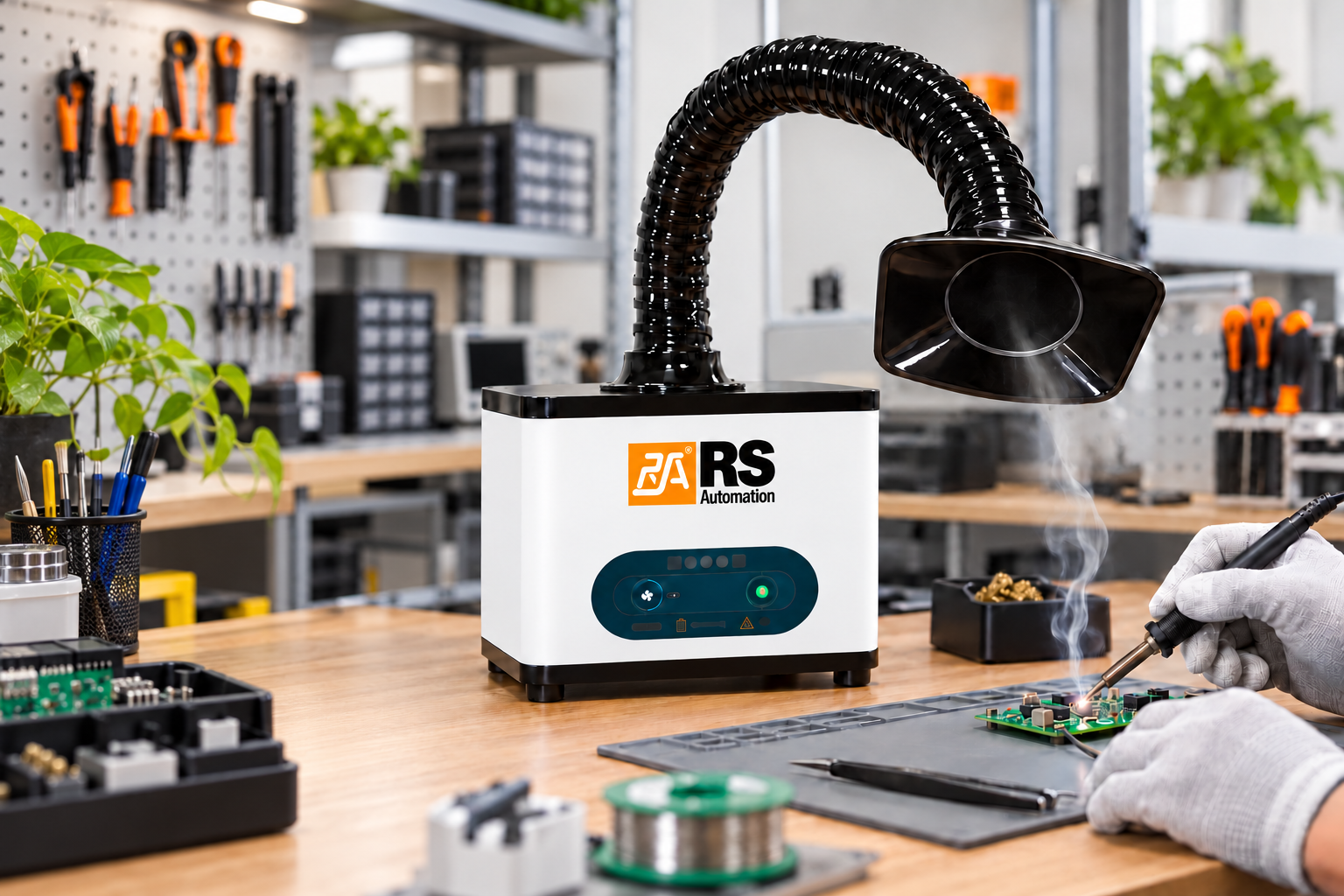
- Identify the source. Mark where the iron, heated wire or solder pot generates fume during normal work.
- Maintain access. Position the arm so operators can load, solder and inspect the part without repeatedly pushing the hood aside.
- Review the airflow path. Arrange the source and hood so collection does not draw fume across the operator’s face. Avoid routing the plume through the breathing zone.
- Check interference. Nearby fans, open doors and workpiece movement may change the path of the rising fume.
- Verify under normal conditions. Evaluate the complete workstation using an appropriate commissioning method, including ordinary operator movements and production materials.
There is no universal hood distance in this guide. The effective position depends on the supplied hood, extraction performance and task. Establish a repeatable position from the equipment instructions and workstation assessment, then include it in the setup procedure. Visible plume movement can help identify an obvious problem, but it is not proof that exposure requirements have been met.
Combine extraction with controlled soldering
The extractor and soldering machine serve different functions. Extraction manages collection at the source; soldering equipment controls the joining operation. Evaluate the RSM-SSM-200A soldering machine with temperature monitoring as part of the workstation layout. Allow clearance for loading, machine movement and maintenance before positioning the extraction arm.

The RSM-SSM-300A soldering machine is another model linked from the extractor product page. Confirm the intended joint, machine configuration and capture arrangement with RS Automation rather than assuming that a product pairing establishes ventilation performance.
Keep joint-quality checks separate from extraction checks. Poor wetting, bridging or inconsistent joints still require investigation of materials, preparation and process settings. Our guide to common soldering defects provides related background; extraction is not a substitute for an accepted soldering process.
Where this fits alongside ultrasonic wire splicing
A harness production line may include soldered connector terminations and conductor splices made by other joining methods. Our ultrasonic wire splicing applications and process setup guide covers a different joining process. Ultrasonic metal welding forms a solid-state joint using vibration and force; it should not automatically be assigned the same flux-fume requirement as a soldering station.
Map each operation individually. Use the assembly requirements to choose the joining method, then assess the contaminants and controls associated with that operation. An extraction requirement at one bench does not establish suitability for every process elsewhere on the line.
Make filter maintenance part of the work instruction
Assign responsibility for checking the hood position, hose condition, connections and filters. Keep a dated record of inspections and replacements. Follow the supplier’s replacement and disposal instructions; do not assume that filters are washable or that every filter stage has the same service life.
A change in collection, abnormal noise, a damaged hose or a recurring odor should trigger investigation. Odor alone cannot establish filtration performance. A fixed replacement interval should only be adopted when supported by the manufacturer and actual duty conditions. After servicing, confirm that filters are installed correctly and repeat the relevant workstation checks.
Prepare an application review
Send RS Automation a workstation photo or drawing, the soldering machine model, flux details, soldering duty, available supply voltage and the number of active stations. Explain any solder-pot or laser operation separately so filter and capture suitability can be reviewed for the actual material and process.
Use the RS Automation inquiry page to discuss the RSE-FP-240, replacement filters and the proposed workstation arrangement. Request confirmation of the supplied configuration and installation guidance before ordering.
Technical references
Model data and photographs: RS Automation product pages checked on October 14, 2026. Ventilation background: HSE guidance on controlling rosin-based solder flux fume and HSE guidance for solderers. These references explain general control principles; they do not certify the performance or compliance of this product.