Wire harness assembly support equipment addresses the tasks around the main cutting, stripping and joining operations: identifying tubing, tightening connector nuts, wrapping local harness nodes, bundling finished products and collecting process fume. Selecting these machines starts with a specific production task and a clear acceptance requirement.
This overview connects five equipment options in RS Automation’s current range with the questions buyers should resolve before a sample trial. The machines perform different jobs; they are not interchangeable, and they do not need to be purchased as one production line.

WHMA’s overview of IPC/WHMA-A-620 describes its role in defining acceptance requirements for cable and wire harness assemblies. When a customer invokes a standard, agree the applicable edition, class and inspection requirements before evaluating samples. Product features alone do not establish that an assembly meets those requirements.
For soldering workstations, the HSE guide to rosin-based solder flux fume explains the need to assess and control exposure, including local exhaust ventilation. Apply the workplace requirements relevant to the installation.
These sources provide general technical context. They do not certify or endorse the equipment described in this article.
Match equipment to the task before comparing models
| Production task | Equipment candidate | First selection question |
|---|---|---|
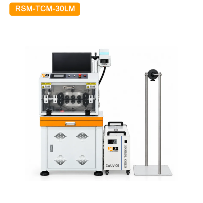
| Mark and cut round tubing | RSM-TCM-30LM | Will the actual tube material produce an acceptable mark and cut? |
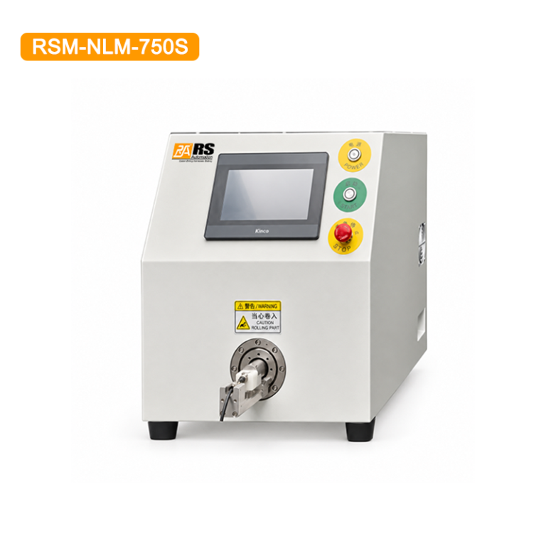
| Tighten a connector nut | RSM-NLM-750S | Can the fixture grip the connector and apply its specified tightening process? |
| Wrap a local harness joint or node | RSM-TW-50A | Can the head access the node and apply the specified tape without moving the wires? |
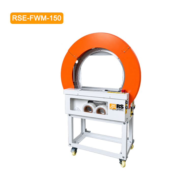
| Bundle products with film | RSE-FWM-150 | Will the bundle fit the opening and tolerate the selected film tension? |
| Collect fume near a soldering task | RSE-FP-240 | Can the hood capture at the source during normal operator movements? |
1. Tube marking and cutting for identification
Tube preparation can involve both identification and dimensional control. A readable mark is useful only if it remains associated with the correct tube section, and a correct cut length is useful only if the prepared piece fits the assembly.
The RSM-TCM-30LM laser marking and tube cutting machine combines tube marking with preset-length cutting. Its published description identifies crawler feeding, a touchscreen-controlled cutting unit and a laser marking unit. Evaluate it using the actual tubing rather than assuming every material or color will respond equally.
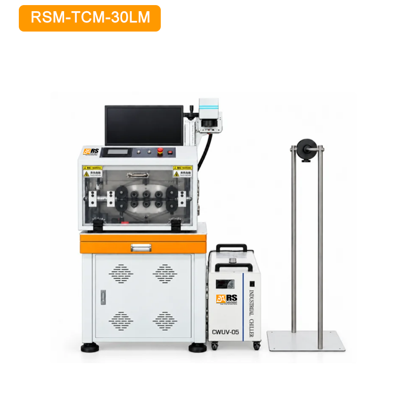
Prepare samples with the required text or code, tube dimensions, material and color. Check legibility, surface condition, mark location relative to the cut, and dimensional consistency. Confirm handling and inspection requirements for the finished pieces. For connector assemblies that use individual insulation sleeves, our D-sub connector preparation and soldering guide explains why sleeves and assembly access should be planned before termination.
For a detailed trial checklist, read our tube marking and cutting machine selection guide.
2. Connector nut tightening for cable assembly
Connector assembly depends on the connector manufacturer’s instructions, not simply on applying a high tightening force. The connector shape, fixture contact points, nut access and required tightening method all affect the workstation design.
The RSM-NLM-750S single-head connector nut tightening machine lists torque, rotation-count and loosening modes, with a 7-inch HMI for parameter settings. Its product page identifies EV charging, PV, ESS, servo-cable and aviation-plug connector applications as candidates for review.
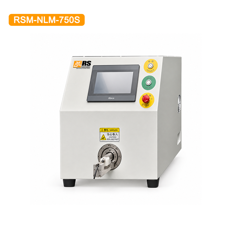
Send the exact connector drawing, component materials, tightening instructions and required checks. Ask how the fixture prevents unwanted rotation or damage and how the process is verified. A torque setting alone does not establish sealing, electrical performance or suitability for every connector in a named industry.
For a detailed trial checklist, read our connector nut tightening fixture and process checks.
3. Spot taping for local wire harness joints and nodes
Local spot wrapping and continuous harness taping are different tasks. A local node needs a defined coverage area, stable wire positioning and a tape finish that fits the next assembly operation. Tape selection and joint geometry matter as much as the wrapping mechanism.
The RSM-TW-50A benchtop wire spot taping machine is described for fine-wire solder joints and nodes, with adjustable winding turns and a production counter. Use a representative node to evaluate loading clearance, wrapping coverage, tape-tail adhesion and removal from the head.
Define the tape material and width, bundle dimensions and acceptable finished coverage. Distinguish the machine’s wrapping time from the complete workstation cycle, which also includes loading, positioning and inspection. Where the node follows conductor joining, our wire splicing applications and process setup guide provides background on the preceding operation. It does not establish that a particular tape or wrapper is approved for every splice.
4. Film bundling for finished-product handling
Finished harnesses and other products may need to remain together during handling or packing. Film bundling should hold the intended arrangement without damaging insulation, connectors, labels or the product surface. It serves a different purpose from insulating a soldered node.
The RSE-FWM-150 automatic film strapping machine lists 50 mm film, adjustable tension, foot-pedal and sensor triggers, and hot-melt sealing. Its product description includes wire harnesses, profiles, cartons and wooden products.
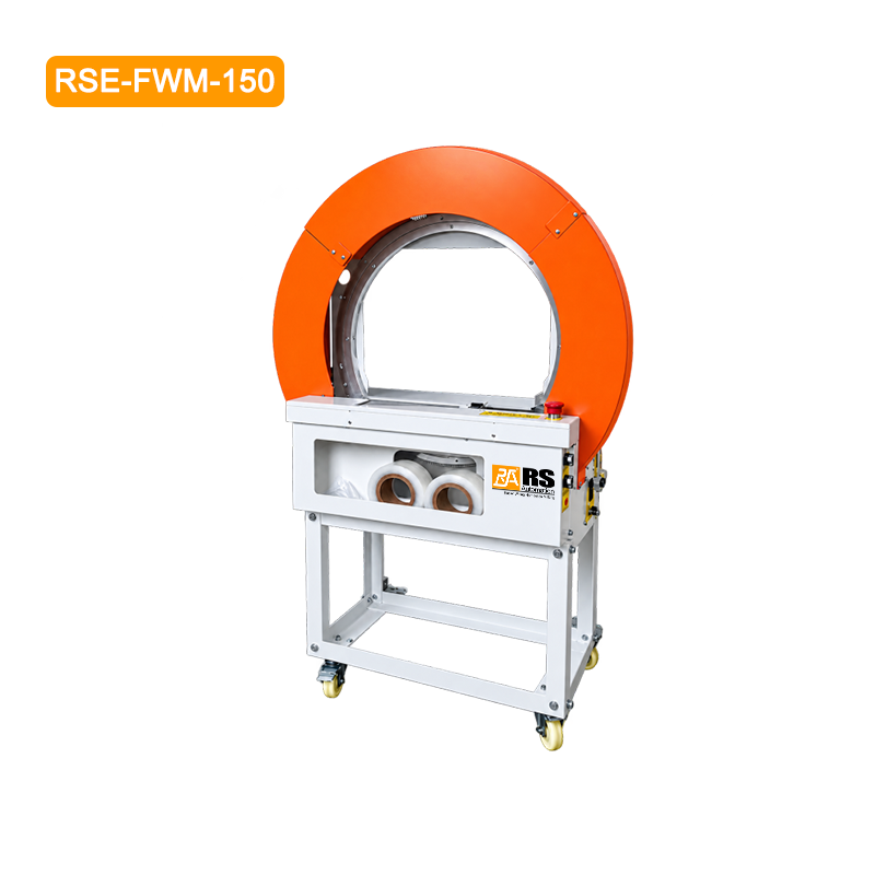
Provide the bundle’s maximum envelope, including protruding connectors, along with its weight and surface sensitivity. Review loading access, the desired number of film loops and how the packed product will be moved. Evaluate holding and surface condition after the trial rather than judging performance from appearance alone.
For a detailed trial checklist, read our film bundling setup and packing checks.
5. Source capture for soldering and related workstations
Workstation support also includes controls around the joining task. At soldering stations, the extraction hood needs access to the source while leaving enough room for the operator and fixture. A compact unit does not automatically suit every bench arrangement.
The RSE-FP-240 desktop fume extractor uses a flexible extraction arm and a multi-stage filter system. Its published configuration is intended for a single workstation. Confirm the actual process materials, filter suitability and hood arrangement before selection.
Read the solder fume extraction setup guide for a more detailed review of placement and maintenance. Do not equate a particle filtration rating with the percentage of all contaminants captured at the workstation. Laser-processing applications need a separate review of the material, emissions and extraction arrangement.
Build a useful equipment inquiry and sample trial
A productive inquiry describes the job the machine must complete, not only the model you have seen. Prepare the following information for each proposed operation:
- Workpiece: material, dimensions, drawings and representative samples.
- Required result: mark readability, cut length, tightening criteria, tape coverage or bundle holding requirement.
- Handling: loading space, workpiece support, operator access and the next process.
- Output: complete cycle target, shift pattern, product mix and changeover frequency.
- Verification: inspection method, acceptance criteria and records needed to repeat the setup.
Keep sample conditions and results traceable to the supplied materials and configuration. If several workstations are being changed, assess the transfer between them as well as each machine’s individual operation. Buying a faster machine will not resolve an unrelated delay in preparation, inspection or packing.
What to record during a sample trial
Record the workpiece identity, machine configuration, tooling and consumables, agreed settings, inspection method and result. Include before-and-after photographs of the same sample where practical. Identify which material and size combinations were tested, and which remain unverified. This makes a trial reviewable and helps separate a demonstrated result from a proposed application.
Questions to resolve before comparing quotations
Should every operation be automated?
Review the current workload and source of variation first. A stable fixture or a clearer work instruction may be needed before automation can be evaluated fairly. Compare the complete task, including preparation and changeover.
Can one sample demonstrate suitability for all products?
A sample demonstrates only the tested conditions. Include the workpieces that represent important differences in material, geometry, size or handling. Confirm the intended operating range with the supplier.
What should the final selection be based on?
Use the required result, representative trial evidence, tooling and maintenance needs, and the complete workstation layout. Published features help identify candidates; they are not a substitute for an agreed acceptance process.
Discuss your next production task with RS Automation
Use the RS Automation contact page to share the operation, drawings, samples, expected output and destination country. Identify the models of interest and ask for a configuration review. The sections above provide a starting point for more detailed application and selection discussions.
Sources and image credits
- Model identity and features: the five linked RS Automation product pages, checked on October 24, 2026. The three machine photographs come from their corresponding listings.
- Assembly acceptance context: WHMA — IPC/WHMA-A-620 for OEMs and EMS providers. Consult the applicable standard and customer documentation for detailed requirements; this overview is not a clause-by-clause interpretation.
- Solder flux fume: HSE — Controlling health risks from rosin-based solder flux fume.
- Industry photograph: “Cable-harness-coaxials-0a.jpg,” Adamantios, 2008, via Wikimedia Commons, used unchanged under CC BY-SA 3.0. Author, source and license links appear directly below the image.
Editorial scope: an equipment-selection overview based on published product information and the references above. No customer trial, certification or measured production improvement is claimed.